philadelphia experiment

My question is WHY someone would want to replicate an experiment that from most if not all accounts created A LOT more problems for our planet than what it solved. That said, for those interested in replicating it, would like to hear what your MOTIVATIONS are. Thank you.
 
Gads. All these years hearing about the "Philadelphia Experiment" and I thought it had something to do with busing school kids around the city.
 
Seems that what was now termed 'philalephia experiment'...was something instigated by a small collect of individuals (it was not instigated by beliek, nichols, von neumann etc) these people never really go into the origins of how, why and importantly WHO stage and funded the experiments.

Regardless, those that did - enlisted the help of 'others' (people not technology or aliens, rather your plain old average joe human) in order to create an intelligent hold on the working. these people were aware and not controlled. it was during the philadelphia exp not montauk. Note i call it a working rather than an experiment.

During the time of montauk, they could access what is termed by the new age as the earths 'girds'. Without this aspect there would be no time travel. The philadelpia experiment had no control over the doorways. Others had to be enlisted to assist. This aspect was kept more under wraps than anything else.

Ask yourself this; why has preston nichols never tried to recreate it will all his knowledge. the so-called time-space-lab of his (some time back) was quite phoney. a delta T antenna hastily stuck on a pole somewhere, is not going to do much by itself. None of these main, alledged participants used to publicise and sell books have really tried. Neither do they dare discuss other parts of the really story behind this much distorted subjct.
 
Well, first of all, as a new member here, Hi there everybody :)

I am in the process (as DoctorZ knows) of trying my own replication of the Philly Exp. (not sure if I should add this) but I found another forum when I was doing some basic research on what I think I would need in order to do this and more info is posted there, but hopefully that will not cause me to be shunned here? I hope not.

So, the first thing, before I get to anything like a full scale replication, I have started to create the drive electronics that I feel I may need to give me a fighting chance of achieving something.... But I shall happily explain what I am trying to do, and how far I have got.

As far as how far I have got..... not very far. That is not to say that I am just talking the talk, I am walking the walk as well, but fitting it in around taking on paying jobs, and also because this kind of thing is quite expensive, I am trying to do it on the cheap as they say.

My current thinking is based on web based research (or the explanation of how the 'myth' is supposed to have worked) I am not sure if any of this story has any validity, but at the heart of it all is a whacking great electromagnetic field.
The initial part of my recreation of this event/myth is to build a smaller scale emf. The original story does mention that the original Philly Exp. used a Sage Radar as this was declassified at the time of the experiment in 1943.


So the current state of the assemblies are as follows:-

1) Low Frequency Oscillator (0-200 kHz)
The electronics of this are all assembled. The Circuit has been tested and is calibrated. The output options are sawtooth, square-wave and sine-wave output with the option to create custom waveforms. This requires the case now printing. The case is a dual skinned case so that a grounded Faraday cage can be incorporated between the skins, whilst maintaining double insulation for safety. Once the case components are completed, they will be assembled and the entire case will be filled with an acrylic potting compound.

2) HF/VHF Oscillator (100 kHz to 450 MHz)
This has been ordered and is arriving as a completely assembled unit. On arrival, I shall remove the carrying handle, check the calibration and then encase this again in a dual skinned case. Again it will incorporate a grounded Faraday cage. The casing for this is going to be a little more interesting to make. It is too big to be printed on my printer, and I can't afford to pay for a custom printed case. Therefore for this one, I do have access to a 3d Router. I shall design the moulds for this, machine them out of 2" thick high density foam and then create a fibre glass case from the moulds, incorporating the Faraday cage by sticking the grounded copper mesh to the fibre glass epoxy during construction.

3) Control System. As both the oscillators have USB control capability, and as I have the ability to create multiple modulated waveforms from a microprocessor, I am including a simple 1 GHz Arm Processor as well. This will allow programmed control if required, as well as also allowing the input from a USB oscilloscope. Each of these units will be connected by screened USB cables running inside grounded copper tubing. This will also allow me to stream live data as well as multiple video streams during experiments. This will be connected by screened Cat5e cable to a hub away from the test area.

4) Power Supply. This again is going to be bought in (order to be placed next week). This is a 24Vdc 5A power supply that will run the Oscillators, the Control CPU and any ancillaries. No Case is needed for this, but it will have mounting brackets made, so it is still an integral part of the test rig structure.

5) Royer oscillator. This is going to provide the high current fields, at typically 5-30 Vdc and up to 25 amps. It will be capable of a very wide band-width by use of inductance coil tuning circuits to minimise any standing wave issues. It is hoped that it will be able to handle the full range of frequencies provided by the two low power oscillators. This is very much a work in progress and is currently only 50% drawn up. This is going to have to be entirely home-made. It will be using IGBT's to give the high frequency switching and will be able to supply 24V P-P at up to 50 A. Circuit and Case need to be made for this.

It may be that I create an alternate Royer oscillator as well, using thermionic valves. This would be able to handle far higher voltages and could include up to 190 Vdc as very high frequencies.

6) HT output. There is also going to be the ability to provide upto 25 Kv outputs up to 125 mA. The HT transformer is already wound, and needs the case, Faraday cage and Silicon potting to be carried out.

7) Coils. I now have a two sets of coils, one pair is 150mm id and 450mm long (6*18") and the other set is 250mm id and 600mm long (10*24") These are made from brake pipe to allow cooling fluid to be circulated during operation. They need to be electro-polished and probably nickel plated. I would have liked to gold plate, but the cost is prohibitive for a first run prototype.

8) Output Patch Panel (to be started) This is to allow the differing waveforms from the various generators to be fed into high voltage or high current oscillators, and also allow the connection of the relevant output to the coil assembly. This will be potted in silicone (due to the HT) and has yet to be designed.


All of the cases are designed or will be designed so that they will all fit into a frame made of slotted extruded aluminium. This will allow common grounding, as well as providing me a way of running all the wiring safely and within grounded copper tubing. Obviously the entire electrical system will be earthed and protected by circuit breakers.

There will have to be some software written for this, and I will be incorporating Gauss detectors for my own personal safety.

Although most of the electronics will end up being potted in either acrylic or silicon compounds, all the possible connection points will be maintained via a (low voltage) patch panel so that I can add other modules later if needed, or to allow modification of the test rig for other EMF experiments.....

As you can see, I am moving forward, but I still have an awful lot to do before I operate the full system. Each of the completed components have been powered up and tested, but not currently as a complete assembly.


More to follow.


I have a test boat (a 190 mm long model of a destroyer escort) and the first plan on completion of the entire test rig is to set frequency sweeps, voltage sweeps, seal up the Faraday cage where the experiment will take place, hit the go button remotely and watch on video to see what happens..... I do plan on working out a way of streaming the video and also all the data streams when I am at the point of trial......


What do I expect to happen? well, I know what I would like to happen, but I really think I shall just create a very powerful inductance heater and I shall see my test vessel vanish not by UFT, but by melting and sinking..... but I am not sure.

I hope this has not bored you too much, and yes I did cut and paste this from my blog to save time.... But as with the original post, if anyone has any questions or observations, please feel free to contact me or post here, and I shall respond as best as I am able.....
 
Hi Phil

I don't see a zero time generator on your list. It might be something to investigate further. Currently I am constructing a zero time generator. I'm interested in the rotating centrifugal force field it will create.
 
Hi Einstein... (wow, that is a greeting I never thought I would use)

I am very new to all of this, and therefore I know that I shall miss things. To be honest, I do not know what a zero time generator is :( ; but I am interested in finding out :)

I guess that the first part of my experiment is to actually work out what the experiment goals are. So, what are my goals? initially to try and see if I can create any effect that is unusual, based on the basic knowledge I have on the original experiment.

As far as I can tell, the original purpose of the Philly exp. was to provide invisibility to what became known as magnetic mines. These are not mines that are held in place by magnets (these are limpet mines); rather a 'magnetic mine' would be triggered by changes in localised magnetic fields. Therefore the mine does not need to touch the ship in order to blow up. This was a known process and was a process called degaussing and was a method to neutralise the residual magnetic field that builds up in ferrous material over time.

I am not sure of the thought processes which led from degaussing to radar invisibility, but it could be as simple as someone saying 'I wonder what happens if we turn this power control all the way up?" because my original source is probably not as in depth as some of you guys on here have been exposed to (my initial source of information is the book by Charles Berlitz) I am probably missing a lot of details.

So the goal of the experiment is simply to try and re-create the experiment based on creating as big an EMF as possible and see what happens. Then analyse the results to see what, if any, next steps are to be carried out.

The problem with this experiment is that there are so many variations on what is believed and what is written. Some stories state that the whole process was purely to ensure the ships were 'invisible to magnetic mines' and that the word invisible has taken on other meanings, such as invisible to radar, or full optical invisibility. Other stories state that the system was never intended to create the effects that it did, and everything that happened was a complete surprise. So, my initial experiments will be to create the most intense magnetic field across a range of voltages and frequencies to see if I can get any effect that remotely resembles the green mist, or a hull shaped depression in the water.

In some of the stories, dimension travel, time travel and teleportation are mentioned..... I guess I will not even really consider any of this unless I can at least create a Green Fog.

So what is the real story and how could I (little old me with a budget of only a few hundred pounds) possibly try to get some definitive idea of what happened.

Some other information that I have received is that my idea for the experiment will not work because I do not have a device for controlling this by use of brain waves...... but I have not heard about this in any of the stuff I have read. So, what can I do? Well, as far as using brain waves, I shall use them only to think with at the moment.

What knowledge do I have about technology of the original experiment, and what knowledge do I have to try and recreate this?

My training is Naval. I was a radio/radar officer. So I have experience of the theory behind the original equipment used. The one consistent fact I get exposed to is that the original Philly Exp. used a Sage Radar as this was declassified at the time of the experiment. The other fact I have hear from more than one source is that there was supposed to be a huge bar magnet 'Weighing Many Tons' and this is used to explain why the listed weight of the Lion and the Eldridge are different.

We know the Sage Radar system operated between 425 and 450 MHz. I have a frequency Generator ordered that can cover this frequency range. But of course a frequency generator is not designed to give very high power outputs. So by coupling the output of the frequency generator to a high power high frequency amplifier, I believe that I can create a high energy EMF. I will create the Royer oscillator with the aim that the oscillation frequency is set by the frequency generator, but I may also create a circuit that is in effect an weld power source output stage. Again with the waveforms being created by the function generators. This has two advantages, one that not being a true oscillator, I can use the full range of waveform shapes. The other advantage is that when you consider the mig welding process, you are effectively creating a dead-short. Therefore I know that this circuit design is going to be ideal for running as a 'modified short circuit' power source and will give me up-to 1000 amps at between 1 to 35 volts. The output of this can be fed directly to the coils in order to generate a high current low voltage EMF, or through a 25000:1 step-up transformer. This has been wound using HT rated silicon wire (spark plug wire) and then dipped in enamel to protect even further against flash over (The HT transformer has been the most expesive single component so far, costing as much as everything else together). The step up gives the potential for 25kV output. Although once the first tests are done I may see how high we can go before it flashes..... if the dielectric strength is good enough, we could in theory have an output of 875,000v...

So on the practical side of the experiment? Once everything is here, assembled and safety checked as far as possible, and the coils are covered with polyurethane tubing (so that conductivity of the water does not change the electrical properties of the coils) then they will be suspended in a small aquarium full of water. One of my destroyer escort models will be floated in the centre of a coil and then I shall hit the power. The destroyer escort models have a slot included to allow me to place a 120mm neodymium bar magnet into the model. Maybe a series of tests with and without the magnet.

Due to the microprocessor control, the plan is to provide a frequency sweep at maybe 5 kHz intervals at a preset voltage; then increase the voltage by 5V and repeat the frequency scan. This will happen from 5 to 35v and then I shall connect the HT output. Obviously the first scan will be at 1v input (25kv output) and maybe increase by 1v on the input until I hit maximum or I get flash over of the transformer.

It will take me a few more weeks (plus two for Christmas) before I am ready to run the experiment. I will have the capability to provide upto 7 streaming video feeds, two channels of oscilloscope, voltage current, and time stamps. All live. I shall be setting up a website just to host this data (I have a few hundred gigabytes free on my server, so will host and record it all there). About a week before I am ready to run the full test, I shall post an invite to allow people to log on and watch...... Success or failure, it will all be done live.....:eek:

Anyhow, Einstein, to get back to your post; If I get something out of this test that looks like it is worth going to the next phase, tell me more about this Zero Time Generator and how I would use such a device......


Cheers Phil.
 
Here is an interesting pdf file I came across:

http://www.stealthskater.com/Documents/Beckwith_02.pdf

Everyone keeps talking about a rotating magnetic field at the heart of the experiment. But the zero time generator is mentioned in the pdf. I've also come across other references in the past to this strange device.

Warren Ellis » Tesla’s Zero-Time Reference Generator

The above link gives a general idea on how to construct a zero time generator. Not something that will be laying around anywhere. But from the picture I can see that the device produces a mechanical oscillation in a rotating pattern. You'll have to fabricate this on your own. Unless you have a machine shop make one for you.

I believe the rotating magnetic field actually produces a rotating weight field. Something very similar to the zero time generator. What I suspect is that one is using positive rotation, while the other is using negative rotation. The two weight fields combine to produce a third field. I suspect this third field is what will produce the anomalous motion through time and space.
 
Hi There again Einstein.... Thank you for that, I have printed this out, and now have some bed time reading....

I shall comment more when I have read it...

I do appreciate any help with this project. Although I am comfortable with the engineering aspects of this, I do know that I have some fairly huge gaps in my knowledge. But fingers crossed, on 'P' day, I shall be listening to everyone as things happen (or hopefully happen). As the data and video is being streamed, I hope to be able to have either a group Skype call, or work out another way or being able to hold a 2 way conversation with everyone during the experiment as well.
 
The above link gives a general idea on how to construct a zero time generator. Not something that will be laying around anywhere. But from the picture I can see that the device produces a mechanical oscillation in a rotating pattern. You'll have to fabricate this on your own. Unless you have a machine shop make one for you.


Well, I have had some excellent reading and thank you so much for the links.

As far as manufacturing any components, I have access to some small CNC turning and milling equipment, and so I can manufacture some of the components myself. I am a wee bit busy as a current project for my 'day-job' is taking some time at the minute, but by the end of this month, or middle of January I should start having a little more time and money available to investigate and experiment in this field a little further. I am blogging as well, and below is a link to my blog.

A Very Practical System. | Paranormalis

I have a lot to think about, and also now more to do, I have to start drawing up and manufacturing some components, but hopefully soon, we should have an experimental generator rig that can be put through various tests to see what we can do.....
 
Phil Wainwright;
Welcome to the site.
It is a breath of fresh air to see someone joining the discussions here who, isn't just touting some off-the-wall ideas they "heard about" somewhere, but is actually doing something physical, an experiment of their own design. Many times, posters have made declarative statements how some gadget they found on the internet "absolutely works and if you don't believe them it because you have a problem, not them". You stated up front:
Phil Wainwright said:
"What do I expect to happen? well, I know what I would like to happen, but I really think I shall just create a very powerful inductance heater and I shall see my test vessel vanish not by UFT, but by melting and sinking..... but I am not sure."
You Sir, for what it may be worth, have my respect.

I have no idea what may come of your experiment and I wish you all the best with it. That you intend to try to demonstrate it live for many to witness speaks volumes. I hope that works out for you. I will be very interested to watch as you attempt your tests.
 
Hi there, sorry for the quiet period.

I have been doing that awful thing, (what is it called???) oh yes, trying to earn a living :D

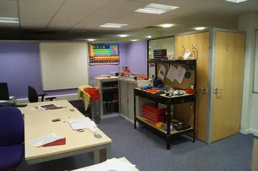
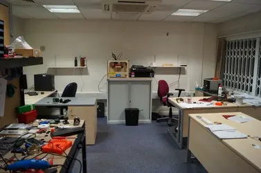
I have also moved offices into a slightly bigger cupboard ;) I shall attach the pics below.

Most of my test equipment is here, and is currently in various stages of assemble across my workbench. We are certainly moving forward. I now just need to get my hands of a Navy Boatyard (or small aquarium if I am going to be really honesto_O )

I really just need to be able to squeeze another 4 or 5 hours a day in, and I may finish soon.....

So, the pics of the office taken today, first official day here, and looking like a bomb site :eek:

office1.webpoffice2.webp
 
Hi there, sorry for the quiet period.

I have been doing that awful thing, (what is it called???) oh yes, trying to earn a living :D

I have also moved offices into a slightly bigger cupboard ;) I shall attach the pics below.

Most of my test equipment is here, and is currently in various stages of assemble across my workbench. We are certainly moving forward. I now just need to get my hands of a Navy Boatyard (or small aquarium if I am going to be really honesto_O )

I really just need to be able to squeeze another 4 or 5 hours a day in, and I may finish soon.....

So, the pics of the office taken today, first official day here, and looking like a bomb site :eek:

View attachment 35View attachment 36


Good luck with your work, Phil Wainwright.

Please remember the formula of "angle of deflection" in the following scientific paper on page 135 (page 27 of the PDF)

http://iiste.org/Journals/index.php/MTM/article/download/2095/2066
 
I will remember as much as possible, and ask when I get to the point of firing up 'stuff'.

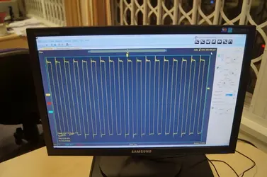
I have stil;l got some assembly to do yet, and also some tweaking.... For example, have a look at the square wave output from one of the Frequency Generators....

waveform1.webp

As you can see, there is a bit of overshoot on the rising edge, and some harmonics along the top edge of the waveform. I think this is just going to be a case of matching the reactive load..... or possibly tweaking the LC network in the generator.

Once I have this one right, I have to do the same with the second frequency generator, and then I have to hook them up to the output amplifiers and then ensure I get the right waveform then as well...... Once I have all of that, I can find my Naval Boatyard and then power up :D

I still have to metallic plate my model ship yet!!!! that I think will take a few days, but need the aquarium to do that......

I know that according to published info, that the USS Eldridge was supposedly a complete vessel, and no wooden parts were left visible, no copper skeleton where the wires were. Therefore it would appear that the differing materials in the construction (wood, copper, glass and steel) are not differentiated against by the field. Therefore, in order to create my conductive hull, I am going to cheat. I shall give the plastic model of the Eldridge a light coat of Aluminium paint, followed by immersion in copper sulphate solution where I shall copper plate the model, followed by a couple of coats of zinc oxide based paint. I think it should give me a nice conductive composite hull.......


Just got to balance this project with work......

:D
 
To get the true feel of the original won't you have to put a "crew" on the ship to see what happens to them? Like a couple of mice or a hamster?
 
Back
Top